
Page 178 - Fluid Power
P. 178
Hydraulic Valves
For any other Part Numbers or Types you require please contact your local Brammer Sales & Service Centre.
Hydraulic Controls
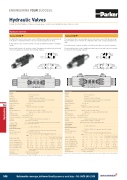
Series D1VW
The NG06 directional control valve series D1VW provides high functional limits up to 80 l/min in combination with a very low, energy-saving pressure drop.
A wide variety of spool options allows to design an unlimited number of hydraulic circuits.
Versions with 8 watt coils, position control, Atex approval, surface protection and connector variants are shown in the following chapters.
Series D3W
The new NG10 direct operated directional control valve series D3W provides high functional limits up to 150 l/min in combination with a low, energy saving pressure drop.
The wide variety of options includes soft shift anchor tubes for smooth operation.
Versions with position control, additional surface protection and connector variants are shown in the following chapters.
Technical data
General
Design
Actuation
Nominal size Mounting interface Mounting position Ambient temperature MTTFD value
AB
Directional spool valve
Solenoid
DIN NG06 / CETOP 03 / NFPA D03
DIN 24340 A6 / ISO 4401 / CETOP RP 121-H / NFPA D03 unrestricted, preferably horizontal
-25...+50
150
1.5 (1 solenoid), 2.1 (2 solenoids)
P, A, B: 350; T: 210 (DC), T: 140 (AC)
Hydraulic oil in accordance with DIN 51524 / 51525
-25 ... +70
2.8...400
30...80
ISO 4406 (1999); 18/16/13 (meet NAS 1638: 7)
80 (see shift limits)
Up to 10 per flow path, depending on spool, up to 15 per flow path for spool type 008 + 009
see table response time
100% ED; CAUTION: coil temperature up to 150 °C possible 15000(notforsoftshift)
IP 65 in accordance with EN 60529 (plugged and mounted)
K J U G Y T
Technical data
General
Design
Actuation
Size
Mounting interface Mounting position Ambient temperature MTTFD value
AB
Directional spool valve
Solenoid
DIN NG10 / CETOP 05 / NFPA D05
DIN 24340 A10 / ISO 4401 / CETOP RP 121-H / NFPA D05 unrestricted, preferably horizontal
-25...+50
150
4.8 (1 solenoid), 6.3 (2 solenoids)
P, A B: 350; T: 210 (DC), 105 (AC)
Hydraulic oil in accordance with DIN 51524 / 51525 -25 ... +70
2.8...400
30...80
ISO 4406 (1999); 18/16/13 (meet NAS 1638: 7)
150 (DC); 115 (AC) (see shift limits)
Up to 20 per flow path, depending on spool
see table response time
100% ED; CAUTION: coil temperature up to 150 °C possible 10000
IP 65 in accordance with EN 60529 (plugged and mounted)
K J U G Y T
18
[°C] [years] Weight [kg]
[°C] [years] Weight [kg]
Hydraulic
Max. operating pressure Fluid
Fluid temperature Viscosity permitted Viscosity recommended Filtration
Flow max.
Leakage at 50 bar
Static / Dynamic
Step response
Electrical characteristics
Duty ratio Max.switchingfrequency Protection class
Supply voltage / ripple
Tolerance supply voltage Current consumption hold Current consumption in rush Powerconsumptionhold Powerconsumptioninrush
Solenoid connection
Hydraulic
Max. operating pressure Fluid
Fluid temperature Viscosity permitted Viscosity recommended Filtration
Flow max.
Leakage at 50 bar
Static / Dynamic
Step response
Electrical characteristics Duty ratio Max.switchingfrequency Protection class
Supplyvoltage/ripple
Tolerance supply voltage Current consumption hold Current consumption in rush Power consumption hold Power consumption in rush Solenoid connection
Wiring min. Wiringlengthmax.
[bar]
[°C] [cSt] / [mm2/s] [cSt] / [mm2/s]
[l/min] [ml/min]
[1/h]
Code
[V]
[%] [A] [A] [W] [W]
[mm2] [m]
[bar]
[°C] [cSt] / [mm2/s] [cSt] / [mm2/s]
[l/min] [ml/min]
[1/h]
Code
[V]
[%] [A] [A] [W] [W]
[mm2] [m]
12V= 24V= 98V= 205V=
110Vat50Hz/ 230Vat50Hz/
12V= 24V= 98V= 205V=
110Vat50Hz/ 230Vat50Hz/
120V at 60Hz ±5
0.8 / 0.72 3.41 / 3.31
240V at 60Hz ±5
0.4 / 0.36 1.75 / 1.7
±10 2.72 2.72
±10 ±10 1.29 0.33 1.29 0.33
±10 0.15 0.15
120V at 60Hz ±5
0.6 / 0.55 2.5 / 2.4
240V at 60Hz ±5
0.3 / 0.27 1.25 / 1.2
±10 3 3
±10 ±10 ±10 1.5 0.35 0.18 1.5 0.35 0.18
Wiringmin.
Wiring length max.
32.7W 31W 31.9W 30.2W 70/70VA 70/70VA
32.7W 31W 31.9W 30.2W 280/290VA 280/290VA
Connector as per EN 175301-803, solenoid identification as per ISO 9461 (code W).
3x1.5recommended
36 36 34 36 88/86 88/86
36 36 34 36 375/397 385/408 Connector as per EN 175301-803, solenoid identification as per ISO 9461. 3 x 1.5 recommended
50recommended
50 recommended
With electrical connections the protective conductor (PE W) must be connected according to the relevant regulations.
With electrical connections the protective conductor (PE W) must be connected according to the relevant regulations.
548
Nationwide coverage, delivered locally same or next day – Tel: 0870 240 2100
Hydraulics
